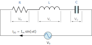
Series RLC circuit acting as a Resistor, Capacitor and Inductor
Series RLC circuit acting as a Resistor, Capacitor and Inductor
When a
resistor R, capacitor C and inductor L are connected in series with a ac supply
voltage, then this circuit is called a series RLC circuit. This circuit can use
in three different ways in practical use.
1. As
inductor
 |
Fig-1: Series RLC circuit |
When
acts a inductor, RLC circuit will show all the properties of an inductor i.e
1.
This
circuit will store energy in the form of
magnetic flux
2.
For
ideal case, Phase difference between current and voltage will be 90 degree.
3.
Voltage
will lead current by 90 degree.
When
acts a capacitor, RLC circuit will show all the properties of an capacitor i.e
1.
This
circuit will store energy in the form of
electric charge.
2.
For
ideal case, Phase difference between current and voltage will be 90 degree.
3.
Current
will lead voltage by 90 degree.
When acts
a resistor, RLC circuit will show all the properties of an resistor i.e
1.
This
circuit will waste or convert energy in the form of heat.
2.
Phase
difference between current and voltage will be zero.
This
three different behavior of series RLC circuit will depend on the supply
frequency. Besides this three different behavior , this circuit will show
another very important phenomenon called resonance, which has extensive used in
our daily practical life in electronic circuit.
Total
current of a series RLC circuit for a known supply voltage v, Resistance R,
Capacitive reactance Xc and Inductive reactance XL will
be
Current, I = v / sqrt{ R2 + (XL± Xc)2 }
Total
Impedance of the circuit will be Z = sqrt{
R2 + (XL± Xc)2 }
And Phase
difference between voltage and current will be
= tan-1{(XL± Xc)/ R }
Now from
the equation of impedance , we see that, total impedance of the circuit
consists of resistance , capacitive
reactance and inductive reactance and we
know the that
Capacitive
reactance Xc = 1 / 2πfC
Inductive
reactance , XL = 2πfL
From
these two expression ,we see that, reactance of capacitor and inductor depend
on the frequency. If supply frequency increase, capacitive reactance will
decrease and inductive reactance will increase but there will be no change in
the resistance of the resistor i.e resistance is independent on frequency
changes.
Inductive Reactance against frequency of
a series RLC circuit:
 |
Fig-2: Inductive reactance against frequency in a series RLC circuit |
From
the graph we see that, inductive reactance increases as the frequency
increases. i.e at low frequency inductor shows less impedance but as frequency
increases , it shows higher impedance .
Capacitive Reactance against frequency of
a series RLC circuit:
 |
Fig-3: Capacitive reactance against frequency in a series RLC circuit |
From
the graph we see that,capacitive reactance decreases as the frequency increases.
i.e at low frequency capacitor shows high impedance but as frequency increases
, it shows low impedance.
Resistance of resistor against frequency
of a series RLC circuit:
For
resistor, resistance constant. i.e resistance does not depand on the frequency
Total impedance of a series RLC circuit against frequency:
 |
Fig-4: Impedance of a series RLC circuit |
 |
Fig-5: Impedance of a series RLC circuit |
From
the graph, we see that, there are two part in the graph.
1. Capacitive part ( on the left side of the graph)
2.
Inductive
part ( On the right side of the graph)
When
frequency is low, then from the graph we see
that , capacitive reactance is high than the inductive reactance and is
still high till a certain frequency fr .This portion i.e between 0-fr
, is called capacitive part of the circuit. In this part , capacitive reactacne will be higher than the inductive reactance and resistance of RLC
circuit and capacitor reactacne will be
dominated and the circuit will act as a capacitor and shows all the properties
that a capacitor can show.
When
frequency is greater than fr, inductive reactance will be higher than
the capacitive reactance and in this portion i.e ( > fr) ,
inductive reactance will dominate and the RLC circuit will act as a inductor
and shows all the properties that an inductor can show.
But
at fr, the capacitive and
inductive reactacne will be equal and opposite and in this frequency only
resistance of the resistor ( in ideal case) will exit and RLC circuit will act
as a resistor and shows all properties that a resistor can show. This frequency
is called resonance frequency. At resonance frequency , impedance of the circuit
will be minimum and maximum current will flow through the circuit.
At
resonance, impedance , Z = R.
 |
Fig-6: Current response of a Series RLC circuit |


Comments
Post a Comment